I started my planning with a rough guesstimate that 2000 square feet would work for me. After several design sketches, I ended up expanding that number to about 2500 square feet. As I played with different track arrangements, it became clear to me that I was faced with several
 choices that modelers with a predetermined layout room are not.
For one thing, aisles weren’t something that I would squeeze into the space left over, but they were something whose width I could determine in advance and then design the track around them.
The next thing I realized is that the depth of any scene on a sincere shelf layout would always average out to about 24 inches. In towns and industrial areas where trackage is dense, it might widen out to as much as 36 inches, but any more than that would require special benchwork to provide access. The shelf would rarely get narrower than 12 inches, because any less than that would provide too little room for scenery.
Any given portion of the layout room would thus always have a fairly regular cross section in between the two containing walls or backdrops. There would be a central aisle with a shelf on either side. I decided early on that a four foot minimum width aisle would be my design target.
Furthermore, it appears that this model yields a relatively constant ratio of room area to model area. Of course this ratio will vary depending on the standards you choose. But if you pick one standard and stick to it, the ratio remains constant. This means that you can work backwards from your layout size goal to determine the square footage required to build it.
In my 50’ by 50’ room, if I lay the track on a two-foot-wide shelf all around the walls, I can have only 200 linear feet of track. I can calculate the ratio of track to room size by dividing the linear
 track length by the square footage of the room, or 200 divided by 2500, which equals 0.08, an extremely low proportion. But it is low because all of the infield space is wasted, and I can get the same length of linear track in a much smaller room, as long as it is no wider than one basic cross section. Such a long and narrow room would be 8’ by 92’, or 736 square feet, and it will still give me 200 linear feet of model railroad track. Now if I divide 200 by 736 I get a ratio of track length to room area of approximately 0.27, a little better than one in four.
But shelves don’t only have to follow walls, and if I have a square room they can extend on a peninsula into the middle exploit the space available there. The peninsula is actually two shelves back to back; one for the track headed into the center and one for the track headed back out. The two shelves are separated by a very thin, common wall, appropriately called a view block. In practice, a view block in a layout this big might be 4 or 6 inches thick, but I will ignore that here for the sake of clarity. Using my 50’ by 50’, 2500 square foot room, we add a single, four-foot-wide, two-sided peninsula extending into the center. While maintaining our four foot wide aisles, the peninsula spirals into the center of the room, utilizing the available space as efficiently as possible. The very end of the peninsula is called a “blob” (yes, “blob” is a very precise term of art in the modeling community), where it
 widens out to allow the track to turn back on itself.
In this plan, the total trackage available is about 670 linear feet. If you divide 670 linear feet of track by 2500 square feet of area, you get 0.268, which rounds up to, surprise, 0.27, the exact same ratio we discovered in our first, minimal example.
It appears that we have discovered a constant. Because this constant ratio measures the portion of the room’s area that is utilized for layout compared to the portion that isn’t, I’ll call it the “utilization constant.”
This utilization constant of approximately 0.27 can be applied to any big railroad room (again assuming you use two foot shelves and four foot aisles). For example, if you have 1200 square feet to build your railroad in, you can know before hand that the optimal amount of main line length you can expect is 324 linear feet, if your
 room’s dimensions are optimal for the shelf depth and aisle width.
Notice that there is very little wasted space on this plan. Except for the single blob, the shelves are never more than 24 inches deep and the aisles are never less than 48 inches wide. If the room were widened by, say, four feet, the added space could not be used as efficiently. That’s because there wouldn’t be enough room to add an entire new leg of the peninsula. For that, we’d need at least four feet for the peninsula and four more feet for the additional aisle. That means that using a two-foot shelf and four-foot aisle, we should only add space in increments of eight feet; no more and no less.
Of course, the ratio will increase if I use, say, 12 inch deep shelves. The ratio will increase dramatically if I narrow down the aisle width, as that is where the lion’s share of the area goes. For smaller layouts, reducing the aisle width is feasible for the simple reason that smaller layouts have fewer, shorter aisles in absolute terms, and smaller layouts are operated with far fewer people, so the congestion is far less. On the other hand, for larger layouts, generous aisle widths are extremely important.
Even if you have a four foot minimum aisle width, on a large layout with a full crew, there is no place within the layout proper to gather everyone together for a briefing or group photo. A
 separate crew lounge for a layout this big should be considered non-optional, but it would still be nice to have at least one really wide spot in the layout room where everyone can gather.
Just for the sake of completeness, let’s look at the ratio if we use aisles that are 36 inches wide. Here’s our simple 200 linear foot layout: It requires only seven feet of width (2 x 2’ for the shelves plus 3’ for the aisle) so the area is 651 square feet. Dividing 200 by 651 yields approximately 0.31. on a full 2500 square foot room, this new ratio holds constant just as before. With only 36 inch wide aisles, this new plan yields another lap of the spiral, so the linear distance
 increases to 784’ in the same area. Dividing 784 by 2500 yields 0.31, which we can see is now our 36 inch wide aisle constant.
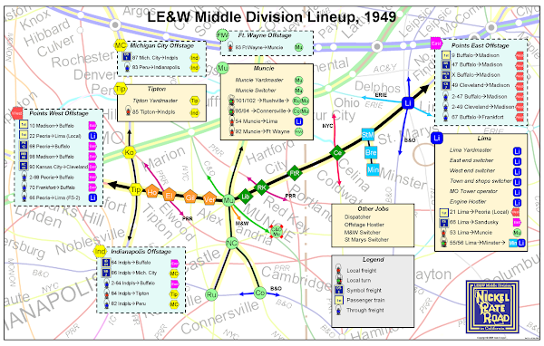
Going back to the 0.27 utilization ratio for my minimum of four foot wide aisles, I can now see what it would take to model the entire 140 mile long NKP Middle Division. If I chose an overall selective compression ratio of one to ten, it would take 850 linear feet of mainline (140 x 60.5’ = 847’). Dividing 850 by 0.27 equals 3148 square feet. This means that it would take a minimum of about 3150 square feet to model the Middle Division in HO using a single-deck, sincere shelf, with four foot wide aisles.
While these two utilization constant examples are interesting, they are based on single deck layouts. For an operations oriented layout, multi-decking is generally considered a worthwhile tradeoff for greater linear track distance. In my next posting, I’ll tackle multi-deck layouts.


No comments:
Post a Comment