Saturday, November 1, 2008

It's 1949

I model the Nickel Plate Railroad in the year 1949 as it passes through West Central Ohio and East Central Indiana. I was born in 1952, so I don't really have first hand knowledge of the times. What's more, I was born and raised in California and my decision to model the NKP was made before I had ever set foot in either Indiana or Ohio.

One of the great benefits of prototype modeling, though, is the opportunity to research a specific time, place, and culture, not to mention a railroad. While preparing a presentation on my layout to the local chapter of the National Model Railroad Association, I did some research into the cultural milestones of 1949. One of the cool things that I found was Frankie Laine's recording of "Mule Train." Laine was a minor country and western singer until he released this song, which some experts claim was the very first pop hit single. The song was a huge hit, and it was a defining audio track for the transition from the war years to the Eisenhower years.

When I was about eight or nine years old my parents gave me a hand-me-down phonograph that looked (and sounded) remarkably like the one in the accompanying YouTube video. Along with the boxy, monaural machine came a couple of dozen hard black plastic records. One of them was Mule Train, and I listened to it for hours.

It was a wonderful thing to rediscover this song after almost 50 years, and it's one of my newest favorites. Go ahead, push the play button and listen to that nasal croon and those unforgettable whip-cracks.

(A big shout out to kjigmond for originally recording and posting this song!)

Sunday, October 26, 2008

The Just Right Connector for Wiring a Tortoise

There have been many different solutions to the minor but omnipresent problem of how to connect layout wiring to Tortoise switch motors. I’d like to show you how I have solved this problem.

The Tortoise slow-motion switch motor is widely popular because it is so simple to mount, simple to wire, simple to control, and because it has such flexible auxiliary electrical connections.

All of the Tortoise’s internal wiring is laid out on an internal printed circuit board, and the end of that board extends out the bottom of the green plastic case, exposing eight metal lands for external connections. The two outermost lands provide DC power to the motor itself: reverse the polarity to reverse the motor. The six inner lands are two, single-pole, double-throw switches that can be used for a variety of creative things, like powering the frog, controlling signals, or informing an interlocking system of the switch’s state. These built-in switches are two important reasons why the Tortoise has been such a successful product.

Evidently, the switches on some of the very earliest models of the Tortoise were make-before-break; that is, they bridged the contact to the new pole before they un-bridged to the old pole. In many different situations, this could cause a momentary short circuit. If the shorting electrical switch is routing DC track power to the frog, it can be annoying, but with DCC track power, such a short is downright dangerous. This was a design error that Circuitron quickly fixed. All Tortoises are now break-before-make, and if you discover one of the old ones, either destroy it or send it back to Circuitron to trade in for a new one (I don’t know what their official trade-in policy is, but if it happened to me I’d demand a replacement). All subsequent Tortoises are absolutely rock solid and very well designed.

Model railroaders are nothing if not creative, and they have devised countless ways to wire up these ubiquitous little green machines.

The easiest Tortoise connection solution is simply to solder wires to the circuit board. However, this approach is problematic because nobody wants to wield a hot soldering iron upside-down under the benchwork, and pre-soldering leads at the bench involves a lot of redundant work that will inevitably have to be redone.

Probably the best solution of this sort that I have seen is to bench-solder eight short (about 12” long) pigtails to the Tortoise, and then terminate them all on an inexpensive barrier, or terminal, strip. When the Tortoise is installed, the barrier strip is fastened to the underside of the benchwork alongside. As the layout is wired up, appropriate circuits can be easily screwed into the other side of the barrier strip to make connections.

The barrier strip is attached to the benchwork with a screw, nail, hot glue, or double-sided tape. It makes a neat installation, but the pigtails are prone to breakage, cold-solder joints, and mis-wiring. Also, there is the cost of the barrier strip and the space it consumes.

At least one company sells a plug-like product that slips directly over the end of the Tortoise’s printed circuit board. You can connect wires to the plug gizmo in advance and then slip it onto the Tortoise at installation time. These little plugs are fairly expensive (around $3 each) because they are not a standard size. This is because the metallic lands on the Tortoise’s board do not use an industry standard spacing, and off-the-shelf PCB edge connectors won’t work. What’s more, it’s all to easy to plug the gizmo onto the Tortoise backwards.

Some people, including me, have tried to create their own plug and jack system by converting the Tortoise’s PCB edge into something more standard. Typically this involves a Molex or equivalent brand crimp connector. The lands on the Tortoise are wide enough to be forgiving of a not-so-perfect spacing match, and a standard eight pin Molex plug works fine if you are careful.

At the bench, you solder an eight pin Molex plug to the Tortoise’s circuit board, then you crimp the appropriate little pot-metal fittings onto the end of the incoming wires, insert them in a plastic jack housing, and slip the jack onto the plug. It makes a very clean and reliable connection, but it is has serious drawbacks.

The crimp connectors are very fussy to use, particularly if you are applying them to several different circuits underneath the layout. They are unforgiving of different sizes of wire, and if you don’t get the lengths just right they can be messy and breakage-prone. The main difficulty with the plug and jack approach is that it solves a non-existent problem while ignoring the most common problem of Tortoise wiring.

The most widely perceived difficulty with Tortoises, and the one that generates the most experimentation with novel connection methods, is the idea that the Tortoise machine itself may fail. If a Tortoise failed, it would have to be replaced, and all of the wiring would have to be tediously unsoldered from the old one and re-soldered to the new one, all while under the benchwork and scenery of an existing layout. While this is a very unpalatable scenario, it turns out to be almost non-existent. I’ve never had a Tortoise fail on me. I don’t know of anybody who has ever had one fail, and I’ve never read of anyone having one fail. In all my reading of the model railroading press and surfing the Web, have found many Tortoise fans praising the machine’s reliability, but never one reporting on a failure. So I believe that adding gizmos to make Tortoise-swapping easy is simply a waste of time and resources.

However, there is one very compelling reason to devise a scheme for a solder-less Tortoise connection. I have never heard or read anyone articulate the problem concisely, so I will attempt it here.

I believe that the biggest practical difficulty of Tortoise wiring is that of connecting several different circuits, each with widely different characteristics, to a single printed circuit board. In a complex model railroad, each Tortoise will typically connect to at least three separate circuits; switch motor power, track power, and signal power. These three circuits will each arrive at the Tortoise from a different source, each will carry widely different types of electricity, each will use widely different types of wire, and, significantly, the physical connection of each to the Tortoise will often come at very different times during the construction of the layout.

Many Tortoises only have two wires connected to them at installation time: the two wires carrying power to the switch motor itself. These are typically 12VDC, are limited to about 30ma, and can be safely carried on very small wires, usually stranded. The wires for this circuit will typically arrive from some remote location. Also, for many layouts, one conductor will be a common ground and the other will be a switched leg from some controller board, each arriving from a different location.

Wires carrying DCC track power, on the other hand, are generally used to switch frog power. The wires for this circuit must carry 14 to 16VDC at 3 to 5 full amps(!), so they are generally larger. What’s more, the wire to the frog will typically connect directly to the rails, therefore it will be solid, not stranded. Sometimes the two DCC source wires will also tap into the stock rails and be solid as well. In many cases, the frog switching circuit is added at some time after the initial installation.

On many railroads, signaling is installed many months or years after the track is first laid. This means that the wiring scheme needed for the signal system may not even be known at the time of initially installing the Tortoise. Signal wiring varies greatly, but it is often very low voltage and very low current, typically 5VDC at some few dozen milliamps. This circuit can be safely carried on the tiny, stranded wires in a CAT 5 cable, and will be quite different from the other wires connected to the switch machine.

Devotees of the Molex approach may argue, but I think that crimp connectors fail to deal with the wide range of wires, at a wide range of times, that must be attached to the Tortoise. Adding crimp connectors to an already installed Molex plug underneath benchwork can be every bit as challenging as soldering under there.

I believe that the best solution is one that lets you do all soldering at the bench, before installation. It will also allow dependable connections to be made underneath the layout with ease and dependability. It should handle a wide range of wire types, sizes, and sources. It should be easy to make changes or additions long after initial installation.

The solution that I have adopted uses a type of terminal block connector made for direct connection to a printed circuit board. It is sometimes referred to as “Eurostyle”. No doubt you’ve seen these little green plastic connectors on various electronic model railroad gizmos. Using them is easy: you strip about 1/8” from the end of a wire, either stranded or solid, in a wide range of diameters, insert the stripped end into a square recess on the terminal block, and tighten the adjacent small screw. The screw pushes down on a small bit of metal that securely attaches to the wire both mechanically and electrically. It’s just as easy to unscrew it and make a change.

It’s a very convenient system, unlike the old-fashioned barrier strip approach mentioned earlier, where you have to bend the stripped end of the wire into a clockwise turn and loop it over a screw head. The terminal block itself is very compact, and the metal tabs intended for soldering through a printed circuit board can easily be laid on top of the Tortoise’s exposed board and soldered directly to it. The Tortoise’s non-standard contact spacing means that the leftmost contact will be positioned slightly to the left of the center of the leftmost land, while the rightmost contact will be slightly to the right of center of the rightmost land, but it’s easy to get it right. Because the whole arrangement is a rigid single block, once you solder one contact in the correct place, all movement ceases and the remaining seven contacts will be guaranteed correct.

There are several different vendors and similar but different models of these connectors, and I’m sure you can find them at several different sources. I purchase mine from Mouser. Officially, it’s called a: 3.81mm 90 degree Kobiconn Terminal block 158-P02EK381V8-E.

These connectors are called 90 degree because the wires are inserted at 90 degrees to the solderable contacts. The screws on this brand have a Philips head rather than a single slot, so they are easier to manipulate.

The price the last time I purchased them was, in quantity one, $2.33 each. In quantities of 50 or more they cost $1.95 each. This may not be the cheapest solution, but it by far and away the best one, and it is also not the most expensive solution.

Just to keep things neat, I use a small, self-adhesive wire clip attached to the size of the Tortoise. This gathers the various wires into a neat bundle leading away from the Kobiconn and routing them towards the underside of the benchwork. I also purchase this clip from Mouser with part number: 561-AWC00375. The clip costs $0.23 and $0.205 in quantities of 100.

All soldering is done at the bench and the wiring can be completed under the layout with just a small screwdriver. Everything is compact and neat and changes are easy. To make this process even easier, I made a little wooden jig that holds the Kobiconn connector against the Tortoise in precise alignment while I solder them together.

Once the Tortoise is installed, it’s a very simple matter to bring the correct wires right up to the Kobiconn connector, cut and strip them to the correct length, insert them into the connector, and tighten down on the screw. Slip the leads under the retaining clip, and the whole arrangement is neat, reliable, and easy to add to.

Breaking news: I’ve just noticed that Circuitron has a new product. It’s called a Smail, and it’s a Tortoise with an on-board DCC decoder, and it appears to have a factory-installed Kobiconn Eurostyle connector soldered onto the circuit board!

Wednesday, October 1, 2008

The utilization constant

The single factor that has the most influence on a model railroad is the space you have available to build it in. the nature of the space has quite a bit of influence, but the size is always dominant. When you have the luxury of building a dedicated, special purpose building to house your layout, the problem manifests itself in reverse. While size is still a strong determinant, and nobody has infinite money or buildable land, you can choose to make the building as big as you need it to be to create the layout you want. You have to ask yourself, “How much layout do I want?” and believe me, you’d better have a good answer.

I started my planning with a rough guesstimate that 2000 square feet would work for me. After several design sketches, I ended up expanding that number to about 2500 square feet. As I played with different track arrangements, it became clear to me that I was faced with several choices that modelers with a predetermined layout room are not.

For one thing, aisles weren’t something that I would squeeze into the space left over, but they were something whose width I could determine in advance and then design the track around them.

The next thing I realized is that the depth of any scene on a sincere shelf layout would always average out to about 24 inches. In towns and industrial areas where trackage is dense, it might widen out to as much as 36 inches, but any more than that would require special benchwork to provide access. The shelf would rarely get narrower than 12 inches, because any less than that would provide too little room for scenery.

Any given portion of the layout room would thus always have a fairly regular cross section in between the two containing walls or backdrops. There would be a central aisle with a shelf on either side. I decided early on that a four foot minimum width aisle would be my design target.
Furthermore, it appears that this model yields a relatively constant ratio of room area to model area. Of course this ratio will vary depending on the standards you choose. But if you pick one standard and stick to it, the ratio remains constant. This means that you can work backwards from your layout size goal to determine the square footage required to build it.


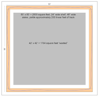
In my 50’ by 50’ room, if I lay the track on a two-foot-wide shelf all around the walls, I can have only 200 linear feet of track. I can calculate the ratio of track to room size by dividing the linear track length by the square footage of the room, or 200 divided by 2500, which equals 0.08, an extremely low proportion. But it is low because all of the infield space is wasted, and I can get the same length of linear track in a much smaller room, as long as it is no wider than one basic cross section. Such a long and narrow room would be 8’ by 92’, or 736 square feet, and it will still give me 200 linear feet of model railroad track. Now if I divide 200 by 736 I get a ratio of track length to room area of approximately 0.27, a little better than one in four.
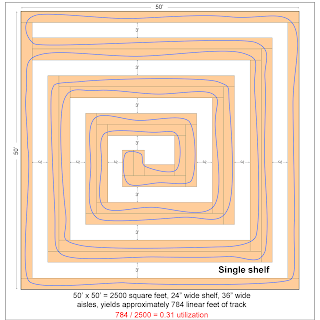
But shelves don’t only have to follow walls, and if I have a square room they can extend on a peninsula into the middle exploit the space available there. The peninsula is actually two shelves back to back; one for the track headed into the center and one for the track headed back out. The two shelves are separated by a very thin, common wall, appropriately called a view block. In practice, a view block in a layout this big might be 4 or 6 inches thick, but I will ignore that here for the sake of clarity. Using my 50’ by 50’, 2500 square foot room, we add a single, four-foot-wide, two-sided peninsula extending into the center. While maintaining our four foot wide aisles, the peninsula spirals into the center of the room, utilizing the available space as efficiently as possible. The very end of the peninsula is called a “blob” (yes, “blob” is a very precise term of art in the modeling community), where it widens out to allow the track to turn back on itself.

In this plan, the total trackage available is about 670 linear feet. If you divide 670 linear feet of track by 2500 square feet of area, you get 0.268, which rounds up to, surprise, 0.27, the exact same ratio we discovered in our first, minimal example.

It appears that we have discovered a constant. Because this constant ratio measures the portion of the room’s area that is utilized for layout compared to the portion that isn’t, I’ll call it the “utilization constant.”

This utilization constant of approximately 0.27 can be applied to any big railroad room (again assuming you use two foot shelves and four foot aisles). For example, if you have 1200 square feet to build your railroad in, you can know before hand that the optimal amount of main line length you can expect is 324 linear feet, if your room’s dimensions are optimal for the shelf depth and aisle width.

Notice that there is very little wasted space on this plan. Except for the single blob, the shelves are never more than 24 inches deep and the aisles are never less than 48 inches wide. If the room were widened by, say, four feet, the added space could not be used as efficiently. That’s because there wouldn’t be enough room to add an entire new leg of the peninsula. For that, we’d need at least four feet for the peninsula and four more feet for the additional aisle. That means that using a two-foot shelf and four-foot aisle, we should only add space in increments of eight feet; no more and no less.

Of course, the ratio will increase if I use, say, 12 inch deep shelves. The ratio will increase dramatically if I narrow down the aisle width, as that is where the lion’s share of the area goes. For smaller layouts, reducing the aisle width is feasible for the simple reason that smaller layouts have fewer, shorter aisles in absolute terms, and smaller layouts are operated with far fewer people, so the congestion is far less. On the other hand, for larger layouts, generous aisle widths are extremely important.

Even if you have a four foot minimum aisle width, on a large layout with a full crew, there is no place within the layout proper to gather everyone together for a briefing or group photo. A separate crew lounge for a layout this big should be considered non-optional, but it would still be nice to have at least one really wide spot in the layout room where everyone can gather.

Just for the sake of completeness, let’s look at the ratio if we use aisles that are 36 inches wide. Here’s our simple 200 linear foot layout: It requires only seven feet of width (2 x 2’ for the shelves plus 3’ for the aisle) so the area is 651 square feet. Dividing 200 by 651 yields approximately 0.31. on a full 2500 square foot room, this new ratio holds constant just as before. With only 36 inch wide aisles, this new plan yields another lap of the spiral, so the linear distance increases to 784’ in the same area. Dividing 784 by 2500 yields 0.31, which we can see is now our 36 inch wide aisle constant.

Going back to the 0.27 utilization ratio for my minimum of four foot wide aisles, I can now see what it would take to model the entire 140 mile long NKP Middle Division. If I chose an overall selective compression ratio of one to ten, it would take 850 linear feet of mainline (140 x 60.5’ = 847’). Dividing 850 by 0.27 equals 3148 square feet. This means that it would take a minimum of about 3150 square feet to model the Middle Division in HO using a single-deck, sincere shelf, with four foot wide aisles.

While these two utilization constant examples are interesting, they are based on single deck layouts. For an operations oriented layout, multi-decking is generally considered a worthwhile tradeoff for greater linear track distance. In my next posting, I’ll tackle multi-deck layouts.

Monday, September 22, 2008

Planning for a Big Space

I’m modeling the Nickel Plate Railroad as it was in 1949. Actually, I’m modeling just one portion, called a division, of just one section, called a district, of the Nickel Plate. My district was the former Lake Erie & Western Railroad, acquired by the NKP in 1926, and thenceforth designated the Lake Erie & Western District. The division I’m modeling is called the Middle Division. It’s not exactly the same as the Middle Division of the old LE&W, because at the time of the acquisition the division boundaries of the LE&W were jiggered somewhat to fit into the existing division structure of the NKP, but the name stayed. The Middle Division runs eastward from Frankfort, Indiana, to Lima, Ohio, a distance of about 140 miles.

I model in HO scale, which is a ratio of 1 to 87. In HO scale an average person would stand about ½ inch tall. That means that one mile of track in HO is 5280 (the number of feet in a mile) divided by 87 or 60.7 feet. To model just the Middle Division, I’d need 8,500 linear feet of track!

Model railroaders use a concept they call “selective compression,” by which they can save lots of space yet still capture the essence of a thing in a model. Basically, you model the visually unique and operationally significant parts of things, while severely truncating or eliminating portions that are either not operationally significant or visually redundant.

For example, a huge meat packing plant might be six stories high and 200 feet square, served by 6 tracks. A good model of it could be four stories high and 50 by 100 feet, served by three tracks. The spirit of the industry is retained while the footprint is dramatically reduced.

The place where selective compression is practiced more than anywhere else is along the mainline. For example, the tangent (straight) track between two towns is cut from 15 miles to a fraction of one mile. The trackage in the towns themselves would also be selectively compressed, but typically by a much smaller amount. In other words, from a modeler’s point of view, the scenery and trackage within the town is of much more interest than the scenery and trackage between the towns.

I’ve been planning to fit my model of the Middle Division into a room approximately 50’ by 50’, or 2500 square feet. By any model railroad standard that is a room of Brobdingnagian proportions. I’ve never even seen a home layout that big anywhere. But even with that generous amount of room, I’ll be lucky to fit one tenth of it in!

Years ago, model railroads were of for the most part imaginary railroads constructed on enormous tabletops and the track looped over, under, around, and through. Trains of every type and description swarmed over the landscape while the proprietor sat at a large electrical control console and sent the trains where he desired. An observer was hard pressed to know where a train would emerge once it entered one of the many tunnels visible. This style of layout is seriously out of date, and has been largely discredited, and is now referred to as “spaghetti bowl” design.

In recent years modelers have placed far more emphasis on duplicating actual prototype railroads and the actual landscape they traverse. What’s more, many modelers, me included, are focused particularly on duplicating the same operating practices the prototype followed with as much fidelity as possible. In other words, we build a model of a specific railroad, and then we operate it like the specific railroad did. Interestingly, operations can be selectively compressed just like scenery or trackage.

Contemporary layout design utilizes a couple of principles that have sufficiently demonstrated their superiority for realism, construction simplicity, and operational verisimilitude. In particular, layouts are built as relatively shallow shelves, and the mainline of the track only passes through each shelf once. Some people call this type of layout a “sincere shelf.” Of course, there are myriad exceptions and variations to these principles, but I’ll avoid them for clarity.

The primary advantage of the sincere shelf is that an operator can walk along with his train, more easily imagining that he is inside the locomotive because the limits to what he can physically see are very similar to what an engineer inside the locomotive’s cab could see. The single track running through a narrow strip of landscape is the moral equivalent of what the real engineer is aware of as he proceeds down the right of way.

Whatever ultimate size and shape my model railroad will be, it will be composed mostly of a very long sincere shelf. It will likely be wrapped around itself in some spiral fashion in order to make the best use of the space. While real railroads go from one point to another in basically a straight line, few of us have model railroad rooms that are eight feet wide and 1000 feet long.

I have learned much about model railroad planning as a result of the many, many (some would claim too many) track designs I have made. Most model railroads occupy only a couple hundred square feet of space, and the lessons such layouts teach us are commonly known. Because I am planning to build a much, much larger model layout, I’m encountering some lesser known problems and opportunities. It is my intention to record those lessons in this blog, so stay tuned.

Sunday, September 21, 2008

I Need More Room

After spending way too much time planning my model railroad I have learned what is the single, most universal truism of layout planning. It is this: No matter how much space you have available for a layout, it is not enough.

This means that while you are taking into account all of the cool things that you will build—the yards, the mountains, the interchanges, the industries—they will always be subject to the bigger, overriding concern of how much room you have in which to build.

If you have only 100 square feet in which to work, you might plan a small, narrow gauge layout. But you will always need a few extra feet to fit in that stamping mill or the interchange to the Class I railroad.

If you have 500 square feet available, you might plan a small section of a division of a big, urban railroad. But you will always need a few extra feet for that staging yard or for the lift bridge across the river in the center of town.

If you have 5000 square feet available (and who has that much room?), you might plan to build an entire division of a Class I railroad as it drives across the Midwest. But you will always need a few extra feet for wide enough aisles to accommodate the 25-man operations crew such a railroad would require.

So the essence of model railroad planning is making deft compromises. It is one thing to plan a layout that is a decent rendition of a portion of some real or imagined prototype. The trick is to include sufficient scenic and operational elements for it to look and run well, along with sufficient space for the people who will need to see it, access it, and run it. But each thing you add detracts from some other thing. It turns out that the solution rarely yields to brute force.

When I spent a few years playing around with high powered model rockets I learned this very same lesson, and it’s the one that NASA wrestles with every day. You start with a simple cardboard tube and a few grams of black powder as propellant. But to bring the rocket safely back to earth you install a parachute “retrieval subsystem.” That subsystem gets the rocket back to Earth in one piece, but it adds weight to the rocket, so you need a slightly more powerful motor. The more powerful motor demands a bigger hull. The bigger hull requires a bigger parachute. The bigger rocket is more sensitive to the timing of the retrieval subsystem, so you need to add a digital G-force sensor to fire the retrieval subsystem precisely at apogee. That digital G-force sensor is expensive, so you add a manual back up system. Both of those systems add weight, so you need a bigger motor, which requires a bigger hull, and around you go, with each system impacting each other system, ad infinitum.

Once you start up that ladder of complexity, the complexity required to support the complexity grows ever more complex. If NASA could add in all of the safeguards required to create a foolproof space shuttle, it could never be built and would never get off of the ground. All spacecraft must therefore make complex compromises in order to be effective. And the same is true for model railroad planning.

I want to model one division of one district of one modest sized railroad. It represents about 140 miles of flat, Midwestern terrain. What’s more, I intend to have lots of room in which to build it; about 2500 square feet. That’s about the size of the average three-bedroom house. That is more room than most model railroad clubs have, let alone most individuals. And yet the main thing I must grapple with in my planning is compromise.

That little kid in the engineer suit


This image is me at about 4 years old. Even at that age I was a nut for trains. My parents obliged me by dressing me up in a railroad man’s outfit of blue striped denim, a billed cap (with the word “ENGINEER” across it), and red neckerchief.

The occasion was my very first visit to a genuine live steam locomotive. It pulled a short train around the Fleishhacker Zoo (in the late 1960s Fleishhacker was renamed “The San Francisco Zoo”). There is an interesting history of the 22” gauge train here.

For the record, as this photo was being taken, I was scared to death by the loudly hissing monster. Eventually I conquered my fear and I always enjoyed outings to the zoo, but my favorite part was always the train.

Saturday, September 20, 2008

Plan D

Oh, those lucky people who live in the Midwest! When they want to build a model railroad, all they have to do is descend into the basement and build a layout.

We Californians don’t have basements. All of our houses are built on slabs of concrete sitting right on grade. It doesn’t freeze here in the winter, so there is no need to get below the frost line. Well, I suppose not having a basement is a reasonable trade off for having balmy winters. But it still makes things tough for a model railroader.

I’ve been trying to build an auxiliary building on my property to house my model railroad and my workshop. The process has been very trying, and I am no closer to having a layout than I was 18 long months ago when we moved to our new house in Portola Valley CA.

In California, modelers often use garages for our model trains. In fact, many local modelers refer to garages as “California basements.” But garages make really bad model railroad rooms. For one thing, they are typically about 20 feet square, which is simply too small for a decent layout. The big overhead garage door always gets in the way. For another, they are not dustproof and dust really screws up model train layouts. And while it’s okay to park your car outside in California, it is really much nicer if you don’t have to.

The best solution is a dedicated, above-ground building. Preferably one with good insulation, lots of skylights, good temperature and humidity control, and lots of electrical outlets. Windows are good because natural light is good, but windows can get in the way of an around-the-walls track arrangement.

Since we moved here, I’ve gone through dozens of plans, but there have really been only two basic configurations. Plan A was a subterranean model railroad room in the back yard behind the house. It would have been about 3800 square feet, with an additional 1600 square feet on top. The lower level would have housed the model railroad in 2600 square feet, with the remaining room dedicated to a modest workshop, divided up into a metal shop, a woodworking shop, and a model shop, along with a small bathroom. The upstairs area would house my office, a crew lounge area, a barbecue area, a pool cabana, and a dispatcher’s office. Plan A died due to its over-ambitiousness.

I don’t want to talk about Plan B.

Plan C was a simple, above ground building constructed on the side of the house. It would be a single story, about 3800 square feet, and it would have about 2400 square feet for the trains, about 1000 square feet for the shop, and the rest for an office and crew lounge. It was certainly doable, but it just didn’t feel like a victory for me. After Plan A, all of the pieces felt too small, too restricted, and too compromised. And it would have been situated right on top of the only place on our property where we could have built a tennis court. After much soul-searching, Sue and I decided to consider Plan D.

We are right now in the process of figuring out what Plan D actually is. But it starts with selling this house in Portola Valley and finding some other place where there is more land and more freedom to do what we want with it. I’ll let you know what happens.